
Intro
When we asked for permission / sponsorship from the Naval History & Heritage Command (NHHC) to dive the USS Moray, we indicated that our primary goal was to build a photogrammetry model.
I knew it would take more than one dive to build a high-resolution model — but I wasn’t sure how many.
The WW1 UB88 German submarine model had taken me more than six dives but I was just getting started with photogrammetry when I was doing. However, it is also a significantly shorter length than the USS Moray submarine (188 feet vs 311 feet). So, I really didn’t know how long it would take to get the right photos.
Some people build photogrammetry models of large wrecks by attaching a camera to a scooter and moving around the wreck on the scooter while taking photos. I have built every one of my models by swimming the wreck which takes longer but I feel it results in a higher resolution model (most of the time).
This post will provide:
- A link to the on-line 3D photogrammetry model
- Screen captures of the model
- Some potentially interesting archaeological findings.
- Detailed process of capturing 4,000 photos across four dives and building the model
- I included this at the end because it is probably too much detail for most readers
Online Model
Due to some limitations of online tools and mobile platforms, I’ve included links below to both a high resolution version of the model (desktops) and a lower resolution version (mobile).
Model Screenshots
Below are screen captures of the model from the Metashape software. First are two full length captures and then some details.


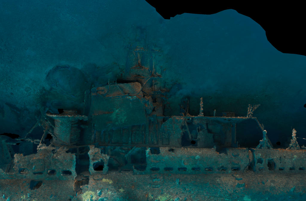


There is a noticeable skew in the front section of the sub forward of the large explosion hole. You can actually see a crack running through the vessel from the torpedo(s) strike as well. It is subtle, but the bow section is rotated at a different angle than the main section of the ship.


Below are two photos of the crack that runs through the ship and you can see the offset. For example, on the left photo, note how the “fin” on the forward section is rotated downwards.


I’m not sure if that “skew” would have been noticed on pictures or when diving the wreck. It really requires an overall view of the entire wreck to see it.
Two Torpedos (?) – aka the Archaeological Benefit of Photogrammetry
We have detailed in the past how photogrammetry can help identify wrecks in “The Case of the Mistaken Corsair” and provide for a record of changes over time of a wreck in “UB88 Orthomosaic + 14 Year Retrospective.”
Another example is how we can use photogrammetry to study a wreck in detail after the dive.
When the UB88 Team originally found the wreck in 2012, the large torpedo explosion hole was very obvious. Below is a detail from the photogrammetry model of that area:


They assumed that there was a single torpedo that hit the USS Moray (which indeed might still be true).
However, Steve Lawson had sent me some documents published by the Navy and 150 pages into a 200 page document was a single sentence that caught my attention (bold type by me):
The ex-MORAY was sunk in 160 feet of water on the coastal side of San Clemente Island in June 1970 by two Torpedo Mk 46 warheads.
Proceedings of the First Conference on the Environmental Effects of Explosive and Explosions (May 30-31, 1973) by George A. Young
Two torpedos.
I started looking at the model to see if I could find evidence of another opening.
Sure enough, it looked like there was a second hole little further back. I did some forensics on that area and believe that it could be from a second torpedo. I’m not sure if it was before or after the primary explosion (or if it is in fact another torpedo hole). Below are screencatpures from the model, actual photos of the area, and GoPro footage.
Model Screenshot

Photos
Here are five untouched photos of the area. In the bottom two photos, you can see divers that are forward of this area and they are at the primary explosion hole. I’m estimating they are about 30 feet forward so I’m assuming it is unrelated to the primary explosion.


Clearly, there is something that exploded in the hull in that area.
Video
This is untouched video of the area while I was taking photos for the model.
Is it conclusive evidence that two torpedos actually did hit the Moray? No, definitely not. However, it does open up the possibility for further investigation.
Detailed Dive Plan & Model Build Process
This section is primarily going to be interesting to people building photogrammetry models or considering it. It has details of my dive plan and dive-by-dive progress.
I spent a lot of time before the dives studying the video that the original team made when diving the Moray. I thought about route plans, coverage plans, tricky areas, etc. My initial estimate was that I would need 3-4 dives to complete a good model.
We asked permission for 3 days not knowing the weather / conditions and how many dives it would take me to build a model but hoped for two dives per day for a total of 6 dives with a little slack just in case.
Dive 1 – On the first dive, I wasn’t sure where the downline would be but it turned out to be amidships near the explosion hole. I dropped down and started taking photos of a large, blank hull and thought to myself, as I looked up at the expanse of the port side of the hull, “there is no way this is going be possible.”
It is hard to describe the challenges of photogrammetry on large expanses of primarily blank hulls. I have also found it much easier to build models of upright ships. After the first dive, I had taken about 1,300 pictures and ran a low-quality alignment process with “generic pre-selection” on my laptop and had the following sparse cloud:

It looked like the bow alignment (to the left) was slightly off. It could have been that it mis-aligned on the sharp angles at the front or possibly due to the kelp on the port side bow, but it wasn’t as dense as the Yukon (which has been causing me fits).
Dive 2 – Given what I had done on Dive 1, I wanted to finish more of the bow and get some more alignment and then work my way along some of he deck area. I took another 1165 pictures and ran a follow-up alignment resulting in the point cloud below.

You can see there is still a problem with the bow and there are a few other anomalies. I did a new alignment with Medium accuracy but still had problems and was starting to worry about the success of the project.
Dive 3 – My plan for dive 3 was to get a lot of the deck section which is a bit tough because it is in the sand and angled downward which means you really need to get up and inside those areas to avoid a big “shadow blob” in the model. I took another 950 photos and figured I would see how “just” the photos from dive 3 turned out with a Medium accuracy level.

This was clearly starting to “go from bad to worse.”
Dive 4 – I got into the water with a lot of worries but a few ideas. I also had thought about the alignment process and figured that maybe if I had a good starting reference point (Dive 2 probably) I might get other photos to align better. I wanted to get more of the underside and torpedo area on this dive, along with the “under structure” areas near the sand on the port side. I also figured that I could get more bow photos in case those didn’t align. I only took about 600 photos on this dive.
I decided to run a Medium quality alignment in “chunks” staring with photos from dive 2 that I knew would align correctly and act as a “reference” point for the other photos. It resulted in the following sparse cloud that I was pretty happy with:

This was starting to look better and took me most of the afternoon / evening after dive 4 (day 2). I needed to know if I could spend dive #5 working on stills or if I needed to work on more images for the model.
I noticed some “ghosting” where things didn’t align perfectly, but figured it was good enough and that I had the raw material that I needed.
Post Dive Model
Once I got home, I could start work on the “real” model. I was in for a little surprise.
I re-imported the photos from all four dives and ran the alignment from scratch on High accuracy on just Dive 1 photos. This was not a good sign:

I then started to think that maybe the divers present in some of the photos were throwing off the alignment since they are not static. I went through all 4,000 photos and masked off any diver so they wouldn’t be used in alignment. I then ran multiple alignment strategies (all photos at once, dive-by-dive, etc.) until I got one that I was happy with.

The model consist of 3,994 photos.
I built a Medium quality mesh with Mild filtering. The depth maps took 4 hours, the mesh took 3 hours and the 8k texture took a little more than 3 hours or a total of 10 hours.
I then decided to build a High quality model with Mild filtering. That was a bit of a mistake. The first time the software crashed. The second time, the computer crashed. The third time, it worked. The depth maps took 18 hours, the mesh took 7 hours and then I built a 16k texture which took another whopping 22.5 hours for a total of 47.5 hours (let’s just call it two days)!
The benefit of the high resolution model is that we can conceivably print a very large version of the model (let’s say 5 feet long) with a large amount of detail.
Thanks To…
Once again, thanks to Ray, Kyaa, and the crew at Sundiver. Thanks to my fellow divers which gave me the leeway and worked around me taking 4,000 photos for the model. Thanks to Tyler Stalter for the teamwork, feedback, and encouragement.
What computer are you using when you build the photogrammetry model?
Onsite, I was using a MacBook Pro (M1 chip) but that was just to check for photo coverage and built a point cloud. For the “real” models, I’m using an iMac Pro with a 3.2 GHz 8-Core Intel Zeon, 32G of RAM, and a Radeon Pro Vega with 8 GB. It is getting aged and I really should/need to buy a new Mac Studio.
If/when you do upgrade to the Mac Studio or something else, it would be interesting to take a photogrammetry project and run it on both the old and the new systems as a comparison, and then write a blog post about it 🤓.
I have nothing against Macs (in fact I’m writing this from a 14″ M1 MacBook Pro!) but I am wondering how well optimized the software is for the Mac GPUs. For something like this, do they run better on midrange Windows GPUs? Or is the fast integrated memory more important? Seems like it would be compute bound, not memory bandwidth bound, but I don’t know. Great models and post!
Yeah, I’m not really sure. For me, it would be pretty impractical to switch to a PC. I do know that Metashape does take advantage of the GPUs in Macsand multi-core CPUs.
Thanks for the comments!
– brett